
Becoming more confident in the low-level encoding, it is time to look at the reproduction of actual bit streams. Our current knowledge, together with the directory listing, strongly suggests an HP system of the 1980s. The call for input brought up some more information on possible disk formats. A colleague (in another city) who worked with HP machines and did some decoding of old floppies gave more hints (he actually wrote a decoder himself a while ago):
Here’s a rough sketchup of what my decoder does:
– Find the sync pattern (several 0x55)
– Swap the bits in each byte (i.e. MSB<–>LSB)
– Look for an address mark (clock pattern always 0x0E)
– 0x70: ID address mark
Calculate CRC16 (initial value 0xFFFF) over four bytes
– 0x50: data address mark
– 0xF0: defective track address mark
– 0xD0: ECC data address mark
– The ID address mark contains the following information:
0: cylinder
1: head in bit 7, sector in bits 5..0
2: CRC byte 1
3: CRC byte 2
Another colleague working on decoding some sample streams replied: “I’m not yet able to extract the sector data, but I can confirm that on several tracks that I’ve examined, the majority of intervals between flux transitions are at 2.0, 3.0, 4.0, and 5.0 microseconds, which matches the expectation for 8-inch M2FM.”
At first we started with the header information (short “sectors” after a sync pattern). We should be able to find the head and track information we have from the Kryoflux output. Sector information is not that easily available, because a track recording does not necessarily starts with sector 0 and usually contains more than just one rotation of the platter.
Identifying the Header Information
This information is contained in the short block after a sequence of 32 binary ones. We did a visual count in the representation of the logic analyzer software. Following directly after the pattern is the identification mark where we found the 0x70 address mark (after bit swapping and reading from right to left) and then the addressing information.
Track (or cylinder) number 31 could be read from the next byte. Both bytes produced expected results which validates the approach so far. For the sector some information was gathered too.
At the end of the data blocks (short and long) some short patterns are visible (after episodes of binary zeros, mentioned by the other colleague) we presumed that could be a CRC. A working CRC algorithm that would give us the chance to verify the data in that particular block.
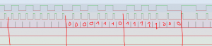
Fig 1: The synchronization sequence is clearly visible, followed by ID and more information.
Track (or cylinder) number 31 could be read from the next byte. Both bytes produced expected results which validates the approach so far. For the sector some information was gathered too.
At the end of the data blocks (short and long) some short patterns are visible (after episodes of binary zeros, mentioned by the other colleague) we presumed that could be a CRC. If we had a working CRC algorithm we would be able to verify the data in that particular block.
Working on the Data
Now we finally come to the significant part. The start of the data sector is the same: initially 32 binary ones, then the marker. Directly after the marker the data stream starts. With the preceding information we have established the proper byte boundaries which should help for further investigation. This cannot be done manually.
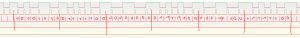
Fig 2: The first filled in bits are the mark (0x50) followed by the data.
The data in this sector is a repeated 0xE3, 0x00 pattern. As the file listing does not include any tracks (cylinders) above 29 (starting from 0), we did not expect to find meaningful information here.
More on the disk format
During the different experiments more facts on the actual floppy disk format were gathered. The disks contain unusual (compared to the typical structure of IBM and PC style disks) 30 sectors instead of the expected 26. These sectors are interleaved and do not follow consecutively onto each other. The flux reading created by the Kryoflux tools contains in their track readings roughly five rotations of the platter. This offers the opportunity to compare different readings of the same sector to each other. This might help if in one reading is the jitter worse or the CRC did not produce confirmation.
Now we are looking forward to our colleague finding some time to extend his scripting for the clocking and coming up with a stream interpreter. An additional benefit would be checking of the CRC values to see if the conversion produced proper results. Now the rather simple structure of the disk (files written flat to sectors) comes in handy. No complex file system structure has to be taken into account to actually reassemble the files.


